From trash to treasure: MPA1004 FET amplifier
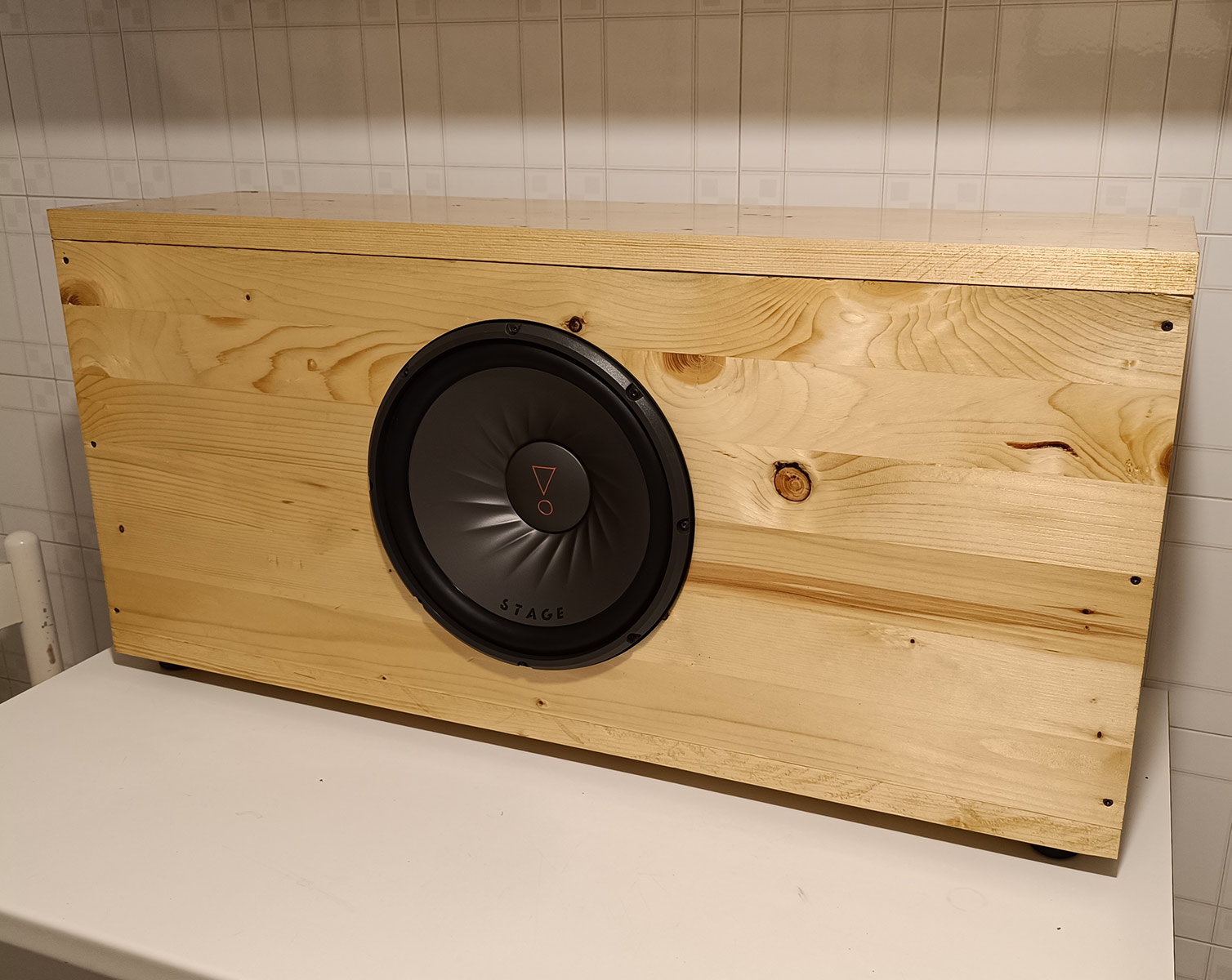
After building such a massive and power hungry subwoofer there was only one problem: finding a suitable amplifier I could use to drive it at full power.
The search stopped when I found a broken legendary DB Technologies MPA1004, 500+500W RMS amplifier on a website for only 40€. I didn’t think about it twice and pretty confident in being able to repair it, I immediately ordered it.
First look
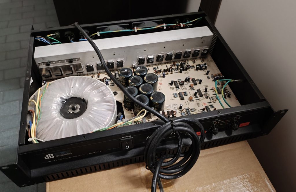
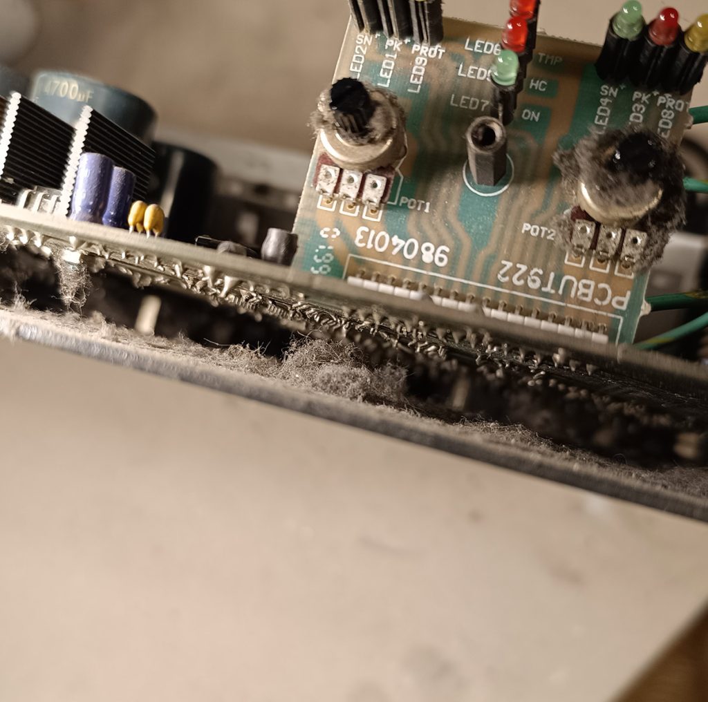
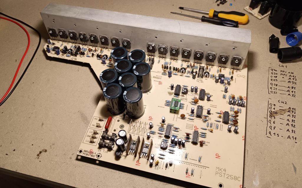
This amplifier is MASSIVE. It has 16 mosfets in total, the old and reliable 2SK1058/2SJ162, but we can see that it was in very bad conditions: all the capacitors were old and bulging, there was so much dust and hair over and under the PCB, plus only 4 mosfets were attached to the heatsink, the rest are just standing there with no brackets at all. Later on we will discover more problems.
The cleaning process
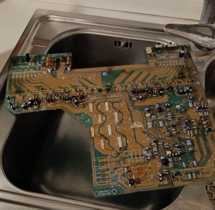
After tearing everything apart and desoldering the mosfets and main components, I decided to literally wash the PCB with some degreaser and antibacterial soap, then quickly rinse it it in 99% isopropyl alcohol to remove any trace of water and prevent oxidation, then dry everything with a hairdryer.

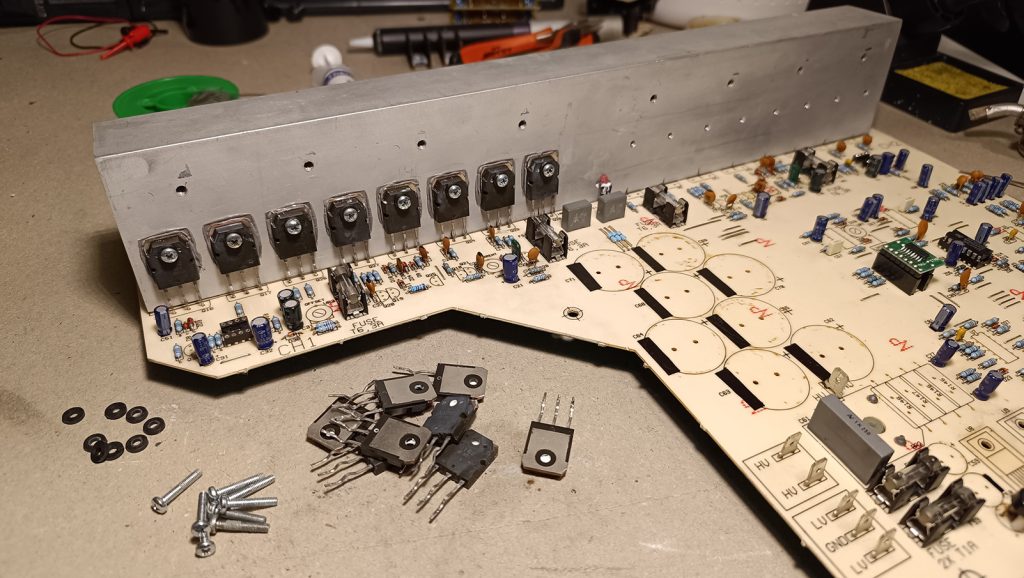
I repeated the same procedure on the aluminum heatsink, then I drilled and threaded by hand all of the 16 individual holes for each one of the mosfets to ensure contact with no gaps and better thermal transfer.
Assembling the PCB
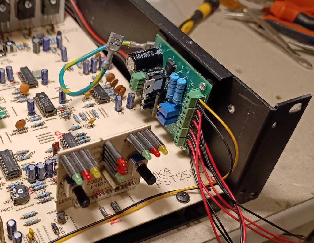
After disinfecting cleaning I started mounting the new components on the PCB.
First I tested all of the mosfets individually, then the various other transistors. I ended up replacing all of the little driver transistors because they were out of specs and with very oxidized and flimsy terminals.
The mosfets were then mounted on the heatsink using M3 screws, mica insulation and high performance thermal grease.
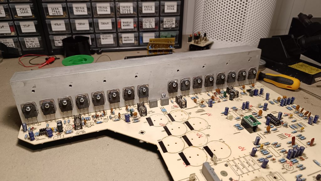
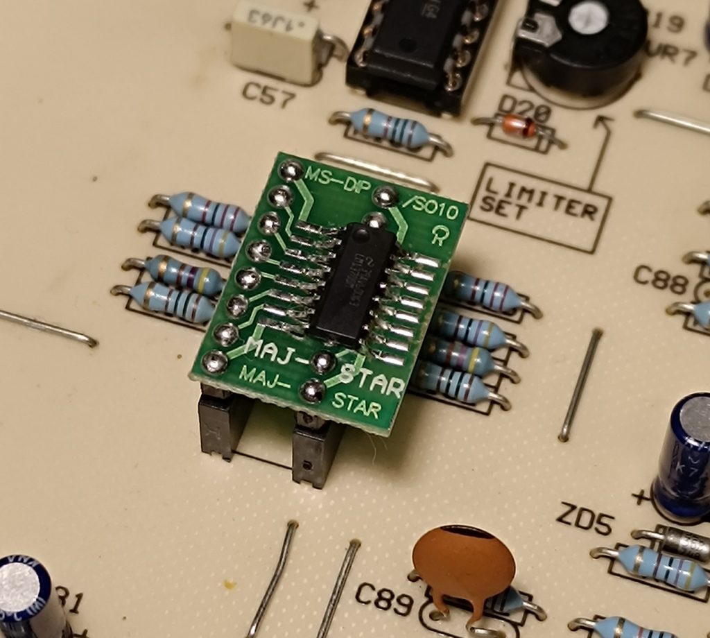
I couldn’t find any NE5517 Dual Operational Transconductance Amplifier so I ended up making a small adapter from an SMD LM13700 to the original pinout and size.
If you click on the second picture you can see the finished board with the new capacitors, new linear regulators, all the op-amps replaced and the 4 input sensing current resistors replaced with some high precision resistive wire. All the trimmers and potentiometers have been replaced as well.
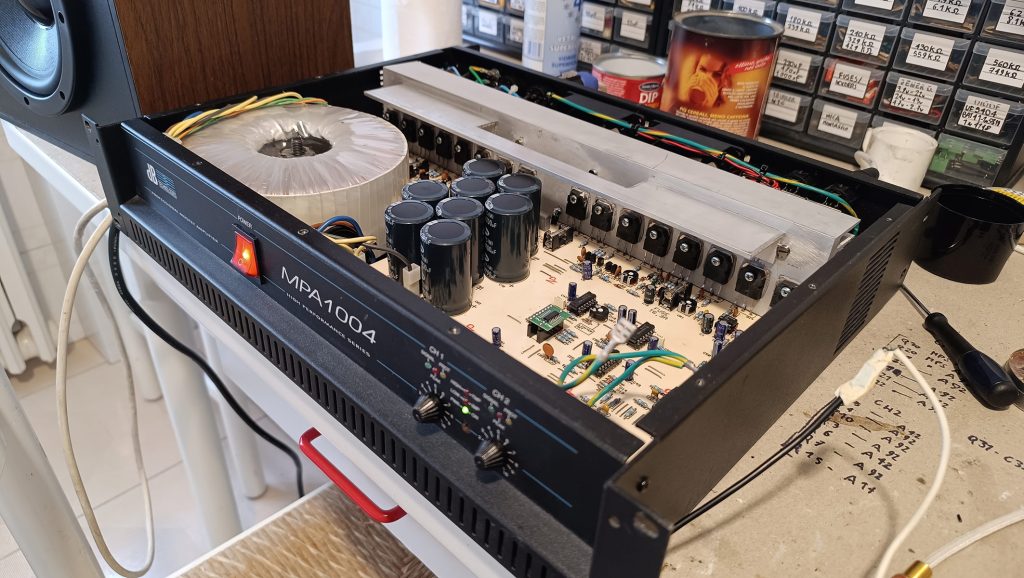
Assembling the unit and offset/current adjustments
I assembled and tested the amplifier, then used the trimmer on the PCB to adjust the offset to make the idle output voltage as close as possible to 0 millivolts.
In this model we can also manually adjust the bias current of the mosfets.
After reading the Hitachi Application Note and comparing it to the circuit of the MPA1004, I could observe that the working principle and implementation is basically the same. This means that the ideal bias current would be of 100 mA per mosfet.
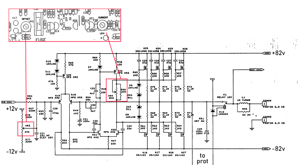
Despite that, due to the large amount of mosfets present and the high (82V) supply voltage this would cause an enormous amount of heat and power loss, so I tweaked the parameters and lowered the bias current to 75mA per mosfet, which gave very good results in terms of heat produced and sound quality.
Modding the case
I could have stopped here: the amplifier works, the sound is clean, the components are not overheating.
But I wasn’t really satisfied with the look of it and there was some improvement that I could do.
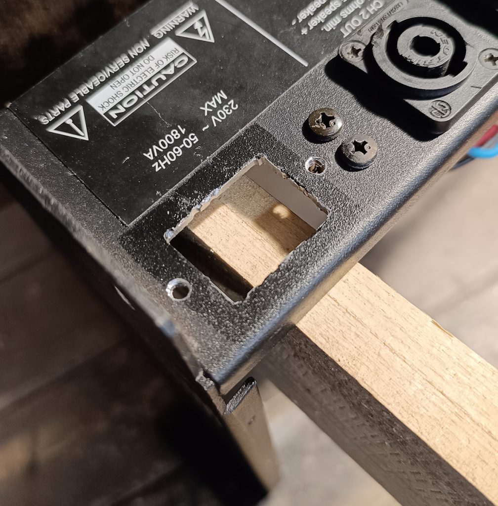
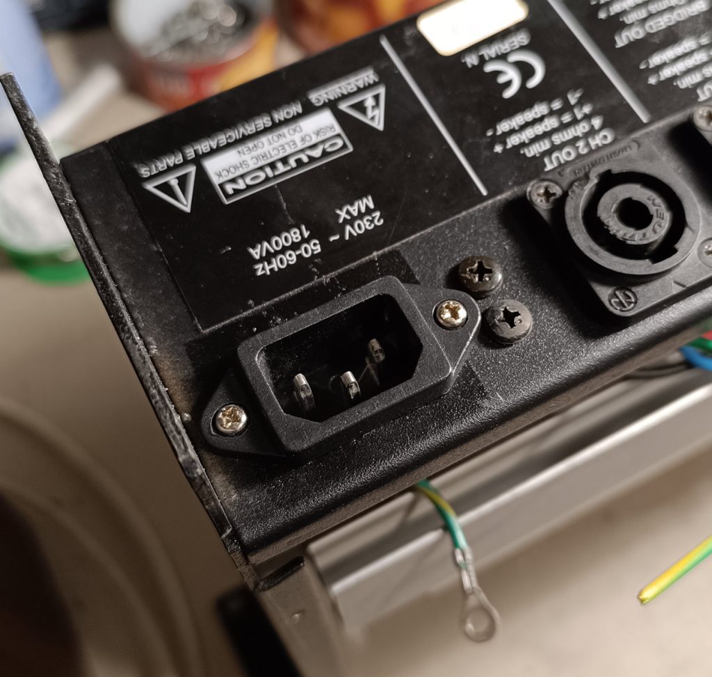
First of all I didn’t like the long power cable sticking out of the back, I wanted something more “transportation friendly”. So I sawed a rectangular hole on the back and mounted an IEC C14 connector.
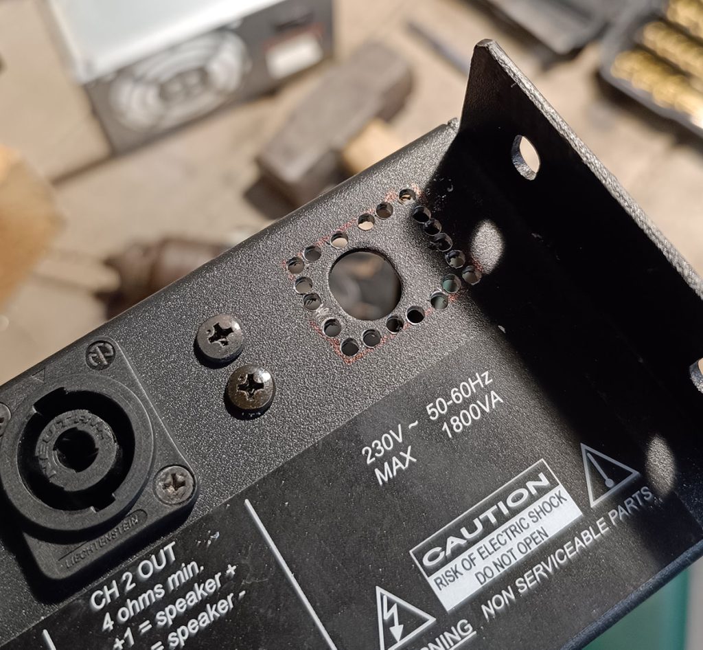
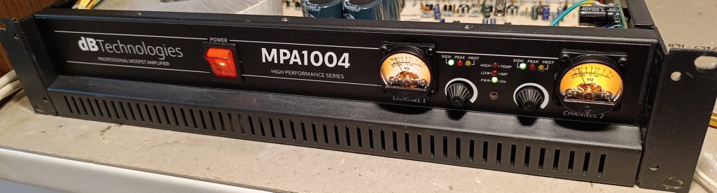
I took the opportunity then to drill two holes on the front panel next to the volume potentiometers to mount two VU meters to have a feedback on the output signal produced.
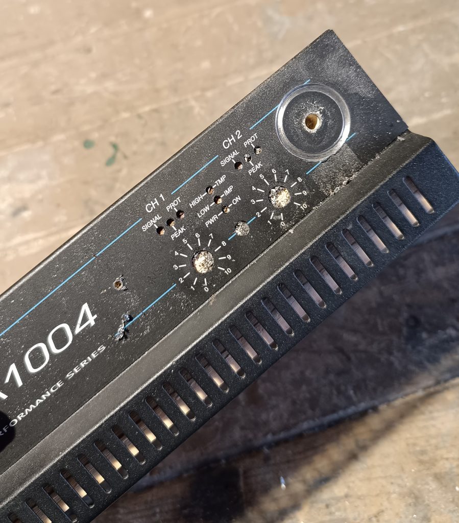
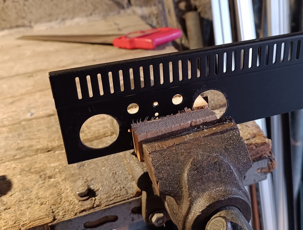
The only problem: the old label did not match anymore with the holes and during the drilling step I had to remove it.
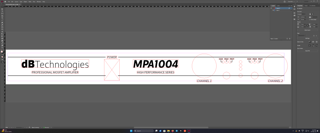
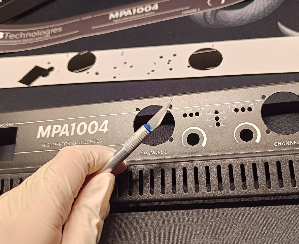
Making a new front panel label
In order to make a new label I first measured the position of the holes and then used the program Adobe InDesign to make a more modern layout positioning the text, volume scale and model number in the right position.
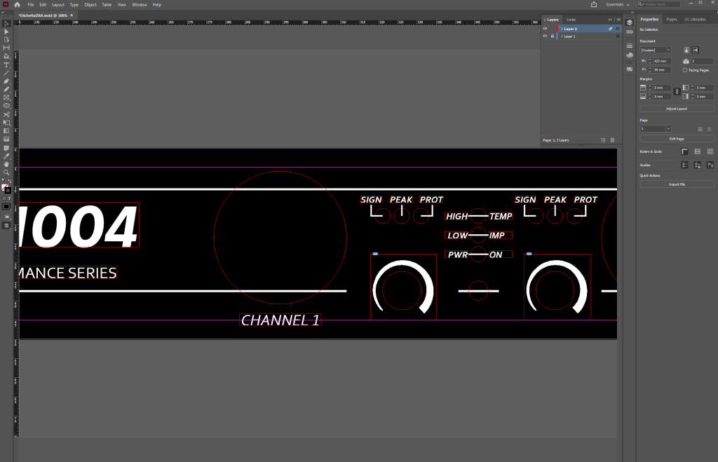
Then printed the label on adhesive PVC, attached it to the front panel and carved the holes using a blade. I didn’t forget to add a control board for the VU meters on the right side.
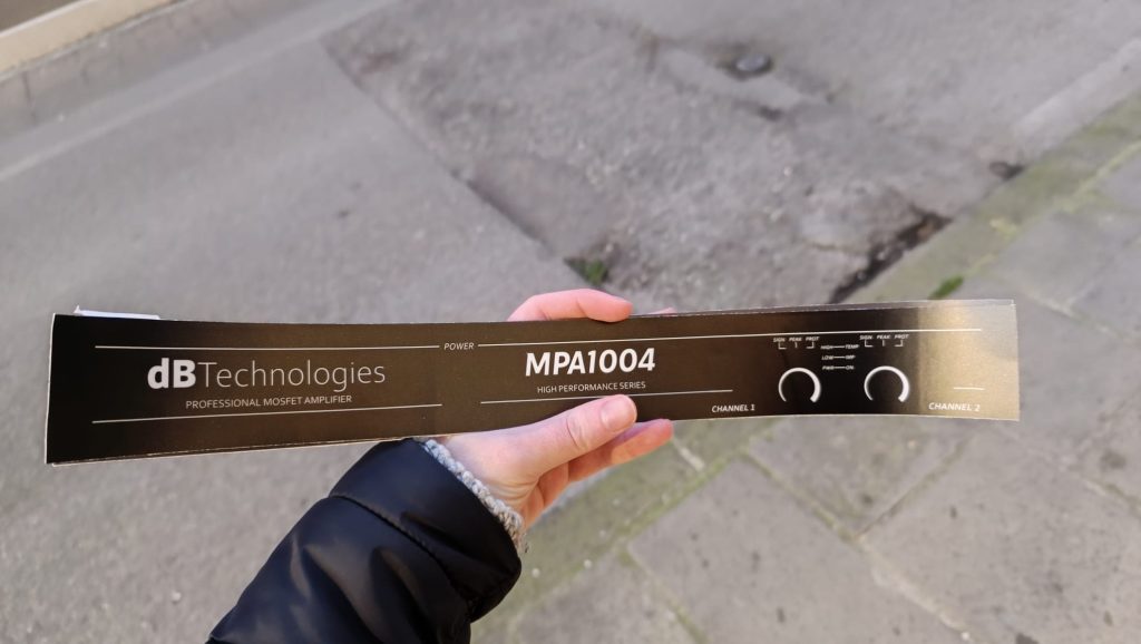
The result speaks for itself
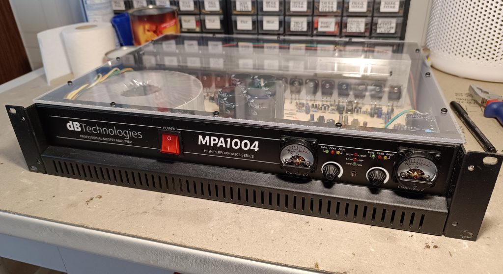
Making the lid and final look
The only thing missing at this point was the lid, in order to do that I simply took a 4mm thick piece of plexiglass, cut it to size and drilled the hole for the screws.
Conclusion
This project took many weeks for completion but that’s quite understandable due to its complexity.
As you read It was a mix of electronics, craftsmanship and design that made all of this possible.
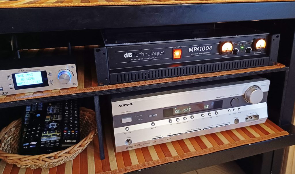
This amplifier is currently in use in my living room connected to the Onkyo TX-SR505E 7.1 Audio receiver to power the large subwoofer mentioned at the beginning of this article. It does its job really well.