Winding a transformer by hand: a nightmare
Probably one of the most frustrating things I’ve ever done, but just for the sake of science and technology, I decided to take an old and broken transformer, remove all the lamination and copper wires and start winding my own transformer using some double enameled copper wire.
Materials needed and winding process
The project is very “DIY”, the inner plastic bobbin was damaged, so I took and shaped a piece of stripboard and glued it to the rest of the plastic. After every layer of enameled wire I used some insulating Kepton tape to separate the two layers, and repeated the process until I was done.
Between primary and secondary windings I used more layers of tape. Overall I used the two whole copper spools, It was very time consuming.
Putting the lamination back
After this unholy task that took at least one entire week, I was left with a chubby conglomerate of copper wires, tape and broken hopes and dreams, but with the help of a vice I was able to squeeze everything together and add the lamination.
You would think we’re done here, but actually not at all. A transformer like this with everything loose vibrates too much, the lamination isn’t secured and the copper windings have air gaps between them, this will cause them to vibrate against each other and eventually ruin the protective layer and KABOOM!
Vacuuming and insulating the transformer
The right thing to do in this case is obtain a vacuum chamber and evacuate all the air from the transformer, replacing it with insulating varnish. I repeated the process 3 times, every time letting it dry and then putting it back in the vacuum chamber to absorb more varnish.
Drying and conclusions
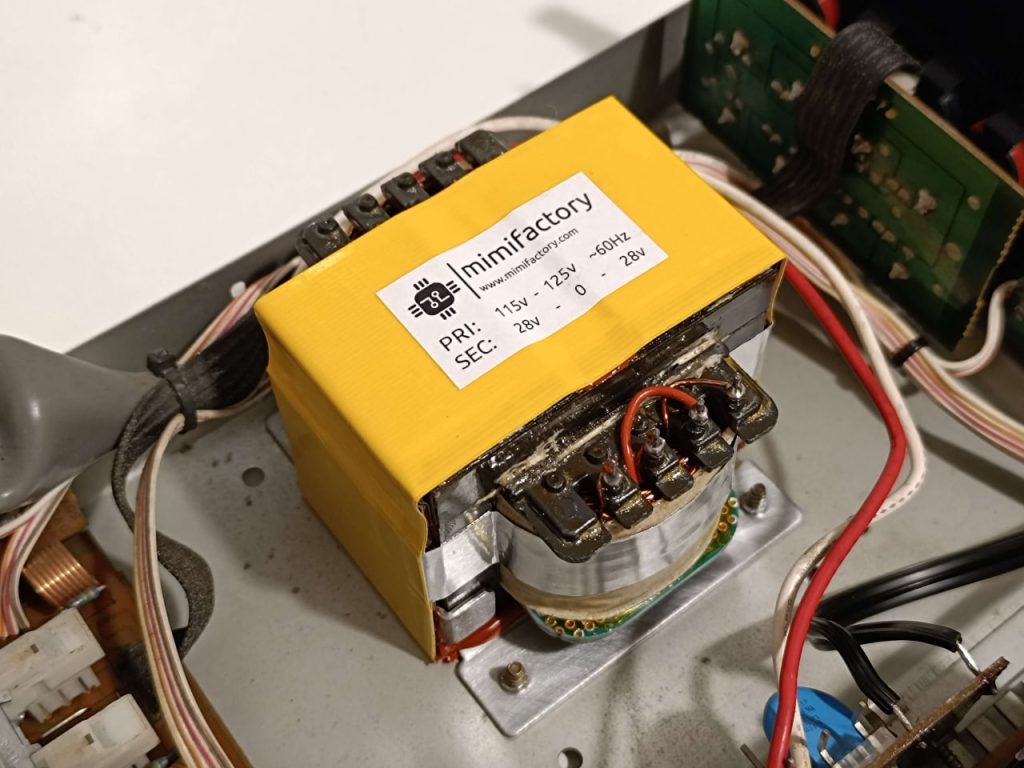
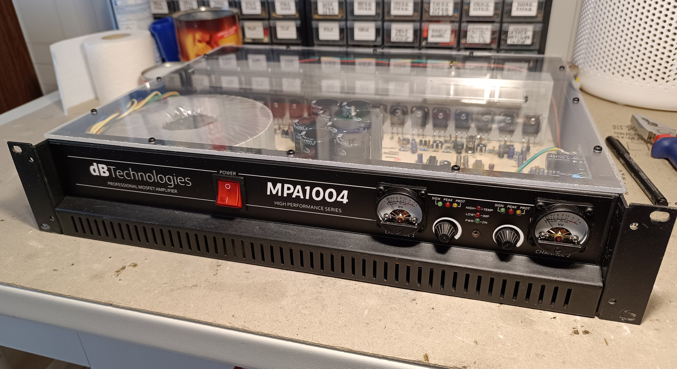
After letting it dry for more than one week, I assembled the final component, tested it with a multimeter and mounted it in the amplifier it was originally in.
I had zero hopes this would work on the first try but, somehow, the transformer is still here, alive and working, after almost two whole years of operation. No vibrations or hum is audible, so the vacuum chamber really did its job well.
Credits and calculations
https://ludens.cl/Electron/trafos/trafos.html provides a very useful tool for calculating the number of primary/secondary windings depending on the material of the lamination used and the flux density.
In this case, a flux density of 1.43 Tesla is used (that’s the minimum amount of flux I could produce with the amount of copper I bought) and the result gives roughly 378 turns on the primary winding and 86 turns on the secondary winding (which we need to double considering the transformer is center-tapped). Overall more than 500 individual turns have been winded by hand.
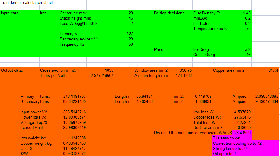
The study of the flux density is important to avoid power losses in the iron core by exceeding the maximum value of magnetic flux allowed by the metal used.
The maximum flux density really depends on the material of the lamination.
Considering the transformer had no label and there was no way to understand the material from the look of it, I sent a few samples to a cool friend of mine to perform a scan of some shavings with an electron microscope and then a material analysis.
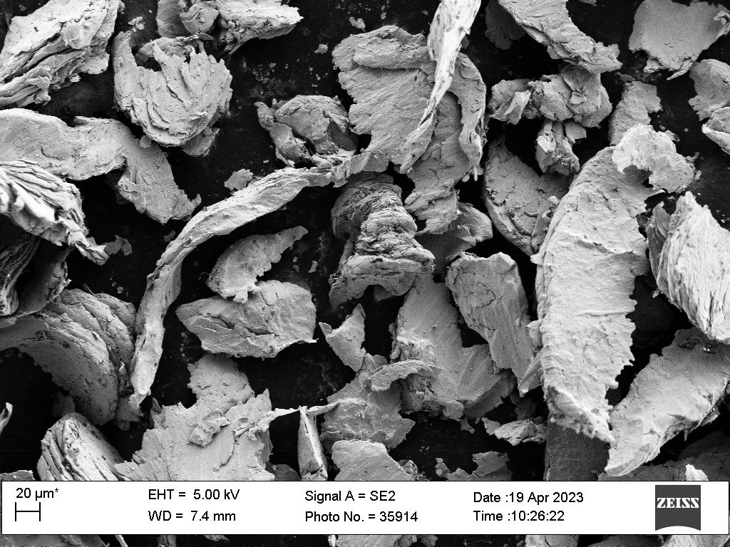
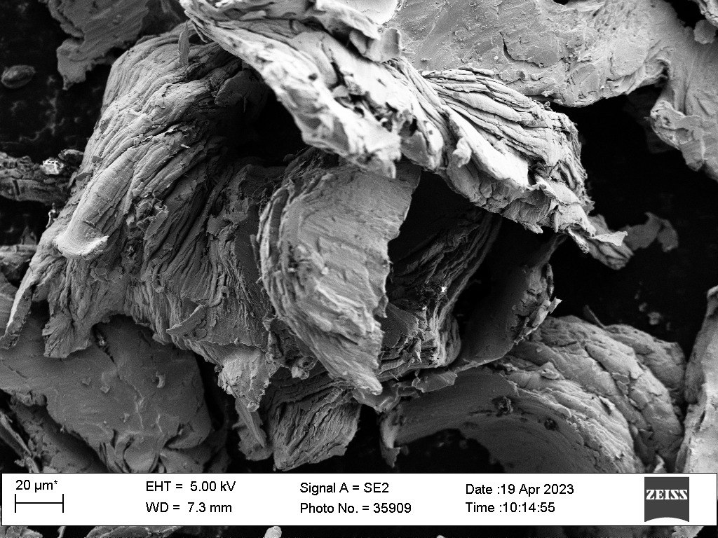
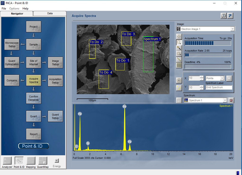
The second picture shows that there is a good amount of Silicon in this lamination, the output file produced by the program tells us that there is a 2.5% presence of Silicon in particular, classifying this metal as Electrical Steel “Silicon Core Iron B” which, according to the datasheet, has a low power and hysteresis loss, making it suitable for high efficiency transformers.
The saturation flux density of this metal is 2.06 Teslas, so the value of 1.43 Teslas I used is perfectly fine for this kind of application.
1 comment